This article explains the design philosophy and specifications of the prototype camera, divided into five sections:
①Specifications
②Material and Precision
③Shutter
④Film Advance Mechanism
⑤Viewfinder
A video showing the full metal machining process from an iron ingot is available on Instagram—please have a look if you’re interested.

①Specifications
Although still under construction, the specifications of the prototype are summarized below.
The first-stage version is scheduled for completion in 2025, and the second-stage version will begin construction in 2026.
The early version includes only the essential functions required for taking photographs.
The later version will add the missing features to improve the overall completeness and usability of the camera.
【Early Version (to be completed in 2025)】
| Format | 35mm full frame |
| Mount | M39 Leica mount |
| Shutter type | Metal-curtain horizontal-travel focal-plane shutter |
| Shutter speed | 1/1000~1/60 |
| Viewfinder | 0.5× real-image finder for 28mm lens |
| Rangefinder | None |
| Film advance | Bottom-mounted pistol-type trigger winder |
| Film rewind | Bottom-mounted crank rewind |
| Film counter | None |
| Dimensions | 140 × 72.5 × 32 mm |
【Later Version (to be started in 2026)】
| Format | ↑ |
| Mount | ↑ |
| Shutter type | ↑ |
| Shutter speed | 1/1000~1sec |
| Viewfinder | None |
| Rangefinder | Real-image coincident type / 1.0× magnification / 120mm base length |
| Film advance | ↑ |
| Film rewind | ↑ |
| Film counter | Additive type, automatically resetting |
| Dimensions | ↑ |
The body dimensions match those of the Leica Barnack type.
While a larger body would make it easier to achieve higher precision and more advanced mechanisms, it would also blur the design philosophy.
The purpose of this prototype is to master the design process and establish machining precision, so I intentionally set a strict constraint by adopting a compact Barnack-size body.
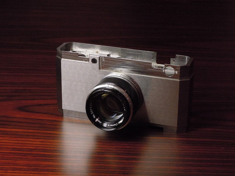
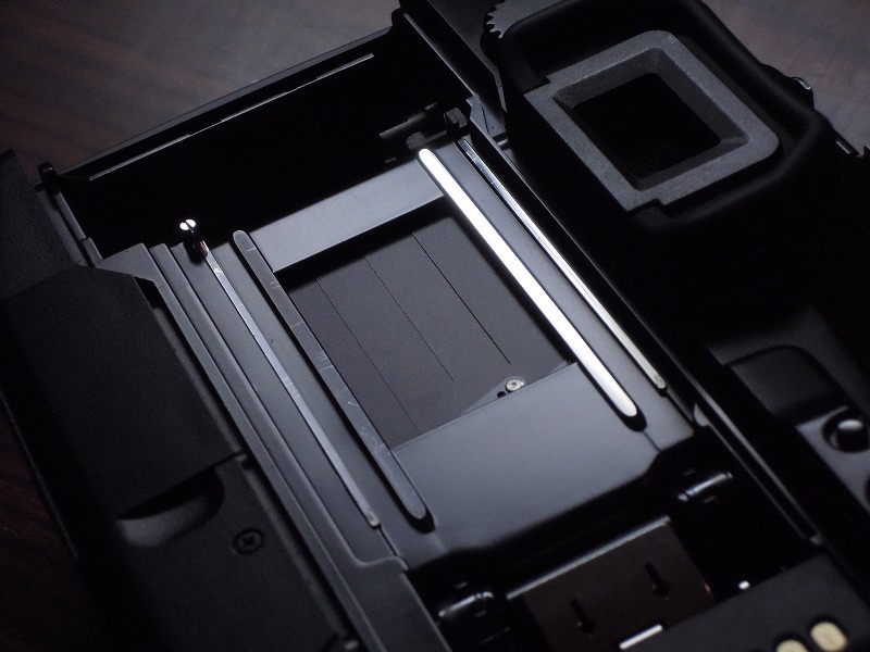
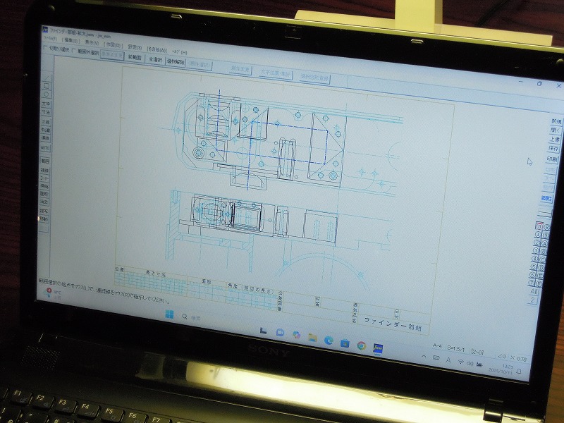
One of the greatest challenges was securing sufficient internal volume for the viewfinder.
While a standard Barnack Leica uses a 0.5× reverse-Galilean viewfinder with a coupled rangefinder, my goal was to incorporate a high-magnification finder and long-base rangefinder into the same compact form.
(Since rangefinder accuracy increases with a longer baseline between the two windows.)
As a result, I was able to achieve approximately 2.5 times the internal volume for the viewfinder compared to conventional designs.
(Fig. 1, Fig. 2: Extended viewfinder chamber)
(Fig.1)
(Fig.2)
②Material and Precision
The body is made of high-strength steel.
Although I plan to use stainless steel or titanium in the future, this prototype intentionally uses steel, which is more difficult to machine than aluminum, as an experiment in achieving precision and rigidity.
Most camera bodies are made of aluminum or magnesium alloys.
By using a high-strength material, it’s possible to improve rigidity, dimensional stability, and machining precision.
Such materials cannot be die-cast and must be fully machined from solid metal.
One of my design goals is to eliminate the need for re-cutting the film rails during the final assembly stage.
In conventional cameras, small assembly errors or distortions are corrected by re-machining the film rails after coating.
However, this process leaves shiny rail surfaces inside the matte black film chamber, causing unwanted reflections.
(Fig. 3, Fig. 4: Film rails in general cameras)
In this prototype, I aimed for such high machining precision that the rails retain perfect alignment after assembly, eliminating the need for post-paint machining.
(Fig. 5: Current prototype body)
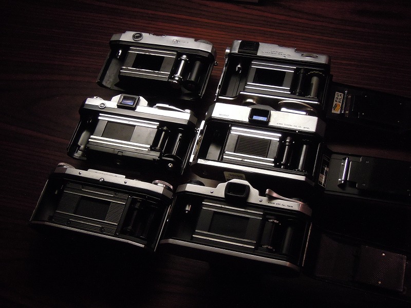
(Fig.3)
(Fig.4)
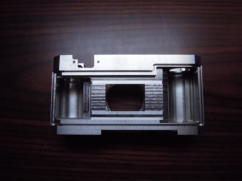
(Fig.5)
③Shutter
The camera uses a single-axis, horizontal-travel metal focal-plane shutter.
Its design focuses on two main points:
・Slit position control
・Reduction of moving parts
・Slit Position Control
Rangefinder cameras require better light sealing than SLRs, so a vertical-travel design was not adopted.
The key challenge lies in controlling the overlap between the first and second curtains.
When the shutter is cocked, the curtains must overlap for light-tightness, but during exposure, that overlap affects curtain speed and exposure consistency.
Ideally, the two curtains should start from the same position and move at the same speed, maintaining an accurate slit width.
This design—used only in a few high-end cameras—ensures both light sealing and precise slit timing.
In this prototype, I implemented this mechanism without adding any extra components.
・Reduction of Moving Parts
In many shutter systems, gears and linked parts rotate together with the shutter drum, creating friction losses and affecting precision.
For this design, I eliminated all rotating elements other than the shutter shaft itself, taking advantage of the simplicity of the single-axis layout.
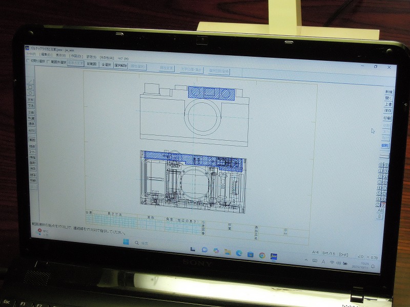
(Fig. 6: Design schematic)
Once complete, this will be the world’s lowest-friction shutter with the fewest moving parts.
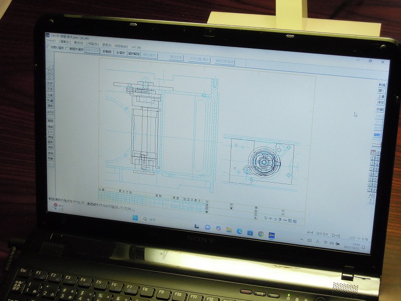
(Fig.6)
④Film Advance Mechanism
The film advance uses a bottom-mounted trigger mechanism, allowing the top section to be dedicated entirely to the large viewfinder assembly.
Key design points include
・Designed from the ground up as a pistol-type trigger system
・Usable even when mounted on a tripod
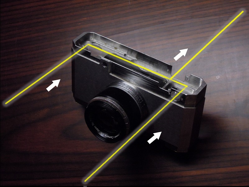
・Film travels from right to left
Most cameras with trigger advances are modified from existing designs, resulting in bulky bodies.
In contrast, this prototype was designed as a trigger-wind camera from the start, using a rack-and-pinion mechanism to keep the body compact.
The trigger can be rotated 90° downward or toward the photographer, allowing film winding even while the camera is tripod-mounted.
The film winds from right to left (viewed from the rear), so the advance mechanism is positioned on the left side of the body.
(Fig. 7: Film travel direction)
The shutter mechanism is located on the right, achieving perfect lateral symmetry—an extremely rare design for a horizontal-travel focal-plane shutter camera.
(Fig. 8: Mechanical layout)
Although splitting the mechanisms left and right usually requires more gears and higher complexity, the rack-and-pinion layout allows simple and efficient power transmission.
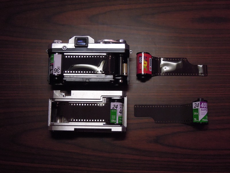
(Fig.7)
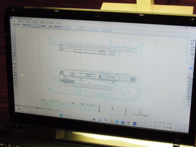
(Fig.8)
⑤Viewfinder
The viewfinder will feature an exceptionally long effective base length, achieving world-class rangefinder precision.
However, since the rangefinder design is not yet finalized, the first-stage prototype will include a 28mm real-image finder (without rangefinder coupling).
The optical layout consists of three objective lenses, three prisms, an erecting lens, and an eyepiece.
Through this stage, I aim to establish the machining and optical alignment techniques needed for lens and prism fabrication.
(Fig. 9: Optical schematic)
A distinctive feature is that the erecting system uses an erecting lens instead of a Porro prism.
Although erecting lenses typically result in lower image quality, the enlarged finder volume allows for a longer focal length, minimizing optical degradation.
In the future, this design could evolve into a variable-magnification finder, using turret-mounted or sliding lenses.
Thus, the use of an erecting lens is also an experimental step toward future development.
The planned rangefinder for the next stage will span the full width of the camera body, achieving the highest possible measurement accuracy.
(Fig.9)